-
The A-scan provides local time of flight from the sample—a time-dependent ultrasonic wave reflected by the component. This information digitizes the selected sample range by means of a previously selected data gate. This data gate for the quantitative time-distance measurement (echo time) is used to set electronic time windows in the depth. Appropriately selected ranges are then incorporated into the C-scan. A digital oscilloscope on the screen represents the incoming echo. If more than one time window is placed (X- or G-scans), multiple images are displayed on the monitor.
-
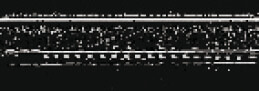
In principle, the B-scan involves stringing together A-scans. They produce a depth-resolved cross-section image of the component in the X direction. The gate is set for the entire time range, but can be configured by the user. With the help of the SAMnalysis software, additional options for the B-scan analysis are provided.
-
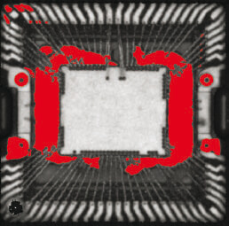
In this case, the gate is set at a specific depth and width (controlled in WINSAM). Scanning the component in the X and Y directions generates a stratified image of the component, whose width corresponds to that of the set data gate. In the event of delaminated surfaces, this area can be marked red immediately (display of phase inversion).
-
-
-
![[Translate to English:] A-Scan](/fileadmin/user_upload/SAM/Images/1a-scan-s.png "[Translate to English:] A-Scan")
![[Translate to English:] A-Scan Signal mit ausgewähltem Gate (rote Box)](/fileadmin/user_upload/SAM/Images/pva-tepla-analytical-systems-ultrasonic-a-scan.jpg "[Translate to English:] A-Scan Signal mit ausgewähltem Gate (rote Box)")
![[Translate to English:] B-Scan-Modus](/fileadmin/user_upload/SAM/Images/pva-tepla-analytical-system-ultrasonic-b-scan.png "[Translate to English:] B-Scan-Modus")
![[Translate to English:] C-Scan-Modus](/fileadmin/user_upload/SAM/Images/pva-tepla-analytical-system-sam-c-scan.png "[Translate to English:] C-Scan-Modus")
![[Translate to English:] X-Scan-Modus](/fileadmin/user_upload/SAM/Images/pva-tepla-analytical-systems-non-destructive-x-scan.png "[Translate to English:] X-Scan-Modus")
![[Translate to English:] Unterschiedliche Tiefeninformation einer IC Probe](/fileadmin/user_upload/SAM/Images/pva-tepla-analytical-systems-sat-x-scan.jpg "[Translate to English:] Unterschiedliche Tiefeninformation einer IC Probe")
![[Translate to English:] Z-Scan](/fileadmin/user_upload/SAM/Images/pva-tepla-analytical-systems-ultrasonic-z-scan.png "[Translate to English:] Z-Scan")
![[Translate to English:] Beispiel einer Bildrekonstruktion aus einem Z - Scan von einer IC Probe](/fileadmin/user_upload/SAM/Images/pva-tepla-analytical-systems-delamination-z-scan.png "[Translate to English:] Beispiel einer Bildrekonstruktion aus einem Z - Scan von einer IC Probe")
![[Translate to English:] Through-Scan](/fileadmin/user_upload/SAM/Images/pva-tepla-analytical-systems-ultrasonic-trough-scan.png "[Translate to English:] Through-Scan")
![[Translate to English:] Transmissionsbild einer IC Probe](/fileadmin/user_upload/SAM/Images/pva-tepla-analytical-systems-microscope-trough-scan.jpg "[Translate to English:] Transmissionsbild einer IC Probe")
